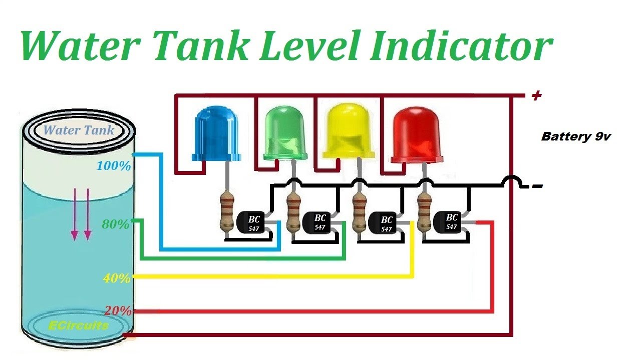
Today we are going to learn a simple and easy to make Water level indicator Circuit using transistors. Genrally, water tanks are installed overhead and there is no way to check how much water level is in the tank, So, due to this water over flow when tank full. This water level indicator circuit that we have suggested is usefull to overcome this problem. In this water level indicator we are going to use BC547 transistor that is most comonly used. You can use and alter of this transistor if want. As an alternative of this transistors are c945, c828, c1815. These all are NPN transistors if you want to use PNP transistor like BC557 you can use but connection will be inverted.

Components for Water level indicator circuit using transitor
The components used in this circuit are very comon and easy to get from old cricuits.
- BC547 transistors-Q1,Q2,Q3,Q4
- Resistors R1,R2,R3,R4-220 ohms
- R5, R6 ,R7 – 100 ohm
- Led – Red(LED3) , Green(LED1) , Yellow(LED2) and buzzer
- Sensor wires – M1,M2,M3,M4.
you can use R1 R2 and R3 if you dont want to use these 3 resistor then you can skip these. You can use buzzer instead of 4th LED.
Water level indicator circuit
The circuit Diagram of water level indicator is given below you can change change this according to your requirements.

Working of Water level indicator circuit
- The circuit is designed to indicate 4 levels of water stored in the tank: low but not empty, half and full but not overflowing.
- If there is no water in the water tank then all the LEDs are off because there is no input of base of transistor BC547.
- When water level increases and reaches A point it turn on the transistor Q1 and D1 LED glows.
- Whne water reaches on Ponit B a small currnt flow form positive to R5. R5 is connected to the base of Q2 so tranistor Q2 turn on and in this way 2nd LED glows.
- In this way all LEDs glow as water leve up and LED turn off as water level drop in the water tank
Note:You can use buzzer if you want and you can increase the numbers of points if want.
Video paractical for Water Level indicator

Leave a Reply