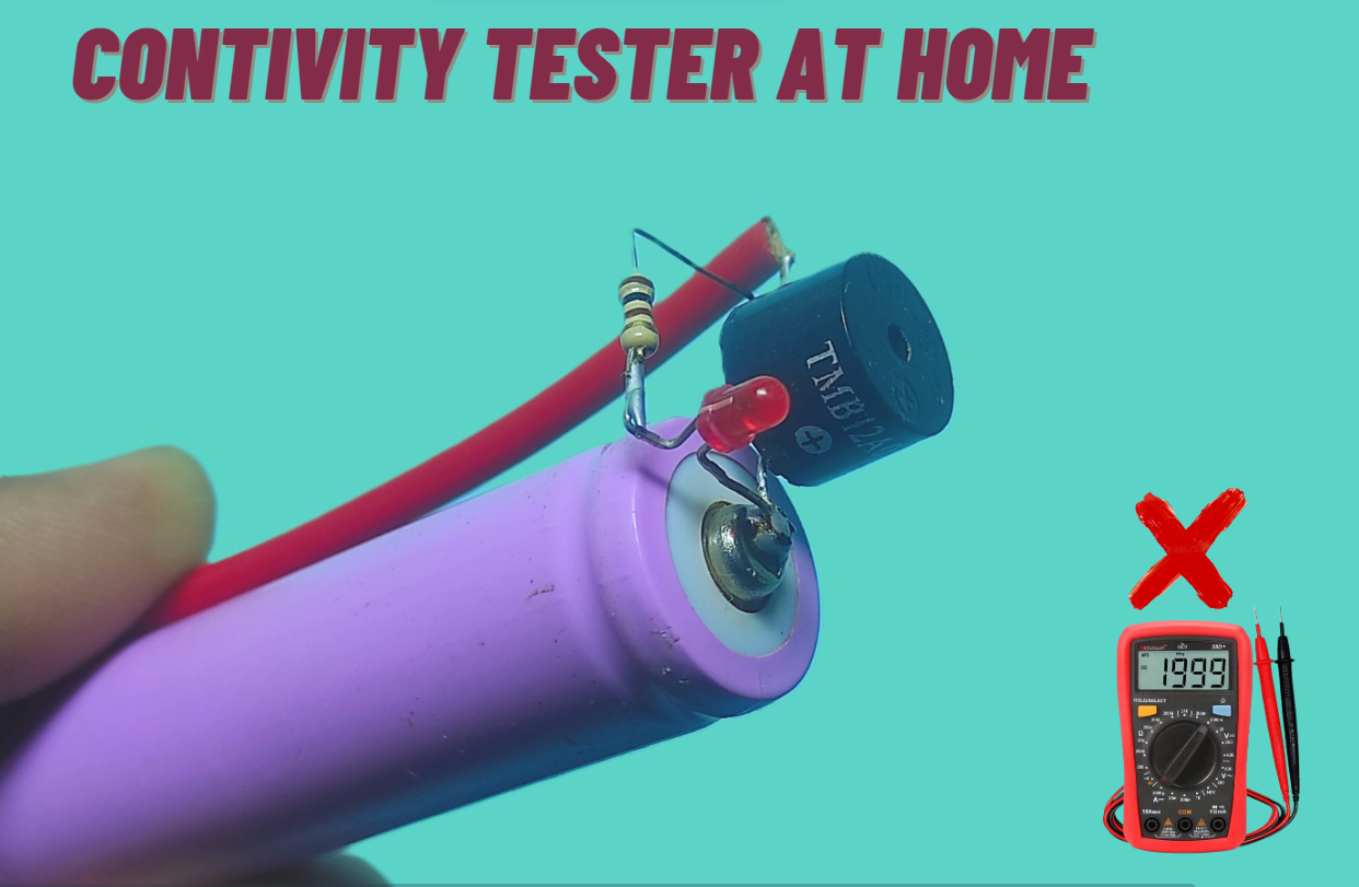
Today we are going to create a continuity tester circuit with a buzzer and LED. It is very important and very liked circuits because we must have to check continuity in many place to run our electronics projects. In this circuit we have used a buzzer and led to show the result.

Suppose, your circuit is not working, it might be due to soldering or any wire breaking. It is very hard to check where actually problem occurring. Continuity tester circuit may become useful in this scenario.
The solder joint problem can consist of disconnect in solder bridge, floating lead, lacking solder, PCB copper etc. The increasing rate of human error because of the decrease in the size of electronic components.
Feature of Continuity tester circuit
The main properties of continuity tester circuit are given below.
- It Can work when the resistance between two probes is lower than 1Ω.
- Other components connected to the point currently tested, that have a resistance over 1Ω will not affect the testing.
- There is only 200uA and 2mV coming from two testing probes. It definitely does not hurt the circuit we are checking.
- Even if we measure across the semiconductor junctions (P-N), it would not affect the circuit.
Continuity tester circuit working
This is very simple and easy to understand. We have used just 2 components 1st is Buzzer and 2nd is LED. Buzzer and LED positive points are connected with the positive point of battery. We have used 100 ohm resistor with LED for the protection of LED. negative points of led and buzzer are connected with the + wire. Negative wire of this tester is connected with negative point of battery.
When positive and negative probes touch each other current flows from negative to buzzer and buzzer start to beep and LED glow also because circuit is complete. In this way we can test LEDs Diodes, wire continuity, and etc.
Parts Required for Continuity tester circuit
- Battery 3v,6v 9v or 12v
- Buzzer
- LED
- Resistor 100 Ohm
- Probes
You may also like these circuits

Leave a Reply