Smartphones charger are commonly used device to charge our smartphones every day. In this post we are going to explain a Cell Phone Charger Circuit Diagram. Every technical mind person want to know how your Cell Phone Charger charger actually works? As we know mobile charger convert AC to DC to charge a mobile phone, for this conversation many components used. In first stage it convert AC to DC and in 2nd stage then it converts into 5v pure DC. Almost all Smartphone charger are 5v.
Simple Cell Phone Charger Circuit Diagram
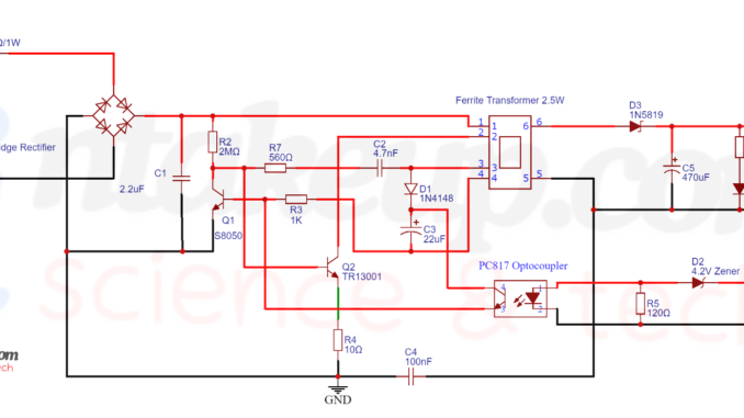
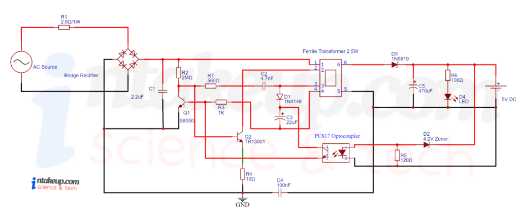
This is Simple Cell Phone Charger Circuit Diagram. There are various circuit diagram of mobile charger here we are describing a simple circuit with PC817C Optocoupler to control the current according to requirements of charge.
Components Required
- Ferrite Transformer
- PC817C Optocoupler
- 1N4007 PN Bridge Rectifier Diode (x4)
- 1N5819 Schottky Diode
- Resistor (2MΩ, 560Ω, 1KΩ, 10Ω, 120Ω, 100Ω)
- 2.6Ω/1W Fuse Resistor
- S8050 NPN Transistor
- 13001 NPN Transistor
- 2.2uF/450V Polyester Film Capacitor
- 4.7nF/100V Polyester Film Capacitor
- 470uF/25V Electrolyte Capacitor
- 22uF/25V Electrolyte Capacitor
- 100nF Ceramic Capacitor
- 4.2V Zener Diode
- Red LED (for indicator)
You may also like
- Motion detector sensor light switch
- Continuity tester circuit with Buzzer and LED
- Water Level Indicator circuit using transistors
- Non-Contact Voltage Detector Circuits Using Transistors and IC
- Transformer less power supply using X-Rated Capacitor
- Water Level Indicator Using ULN2003


Leave a Reply